Archive for the ‘Heat Recovery System’ Category

Sep 9 2008

Heat Recovery System Pipework, – Joining up the last fiddly bits

1

heat-recovery-in-bends.jpg 
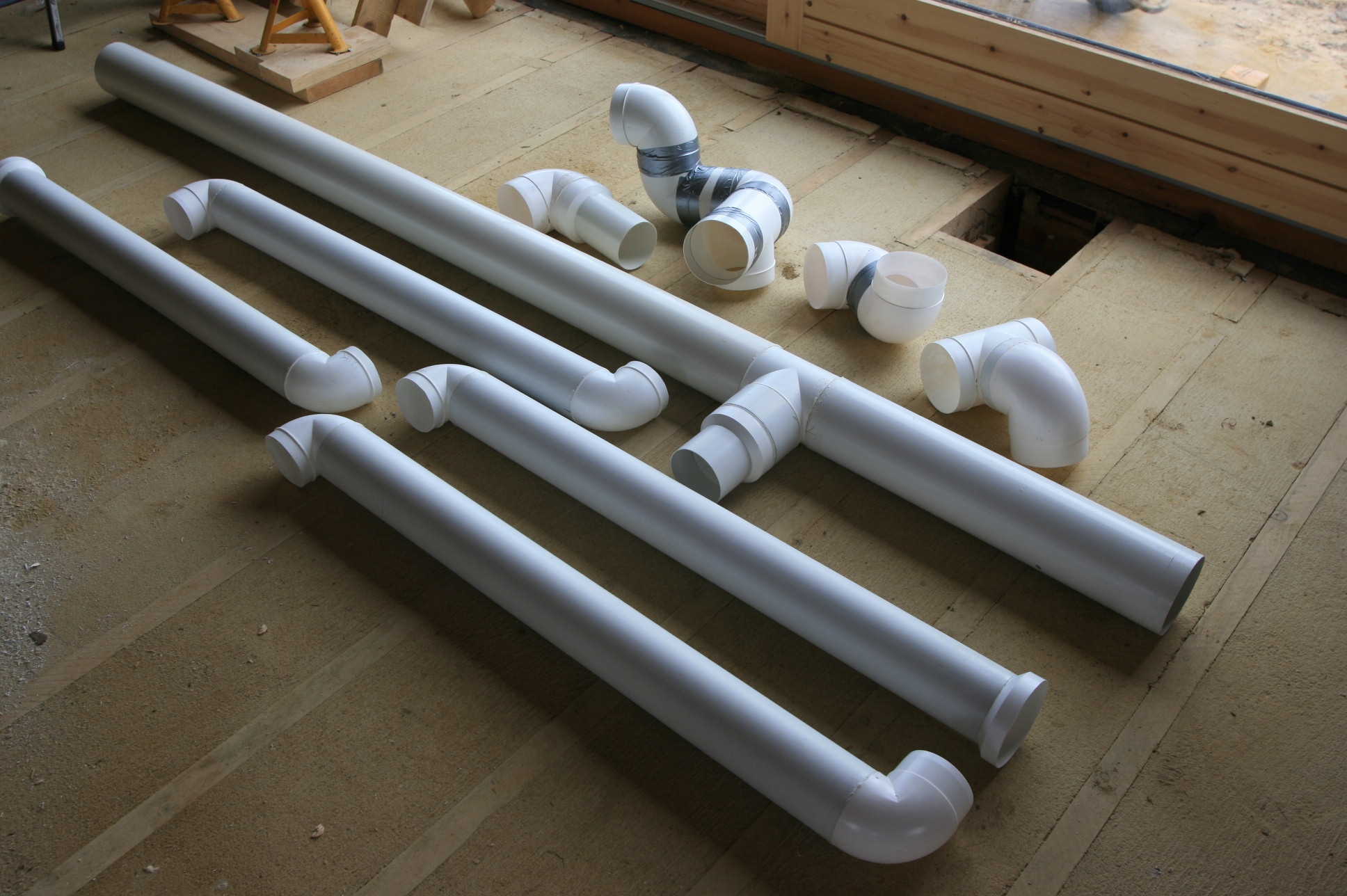
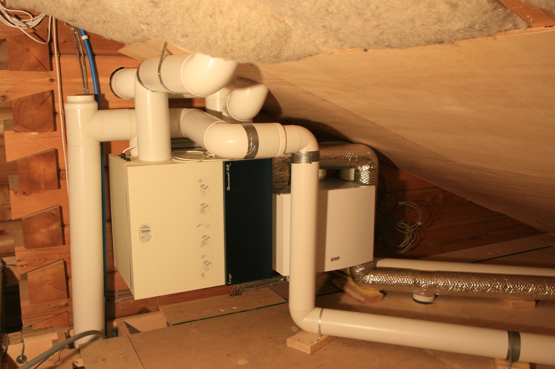
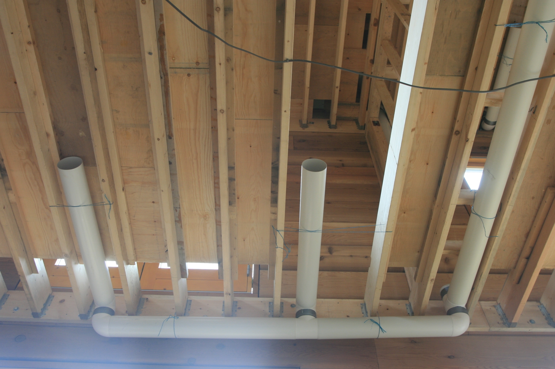
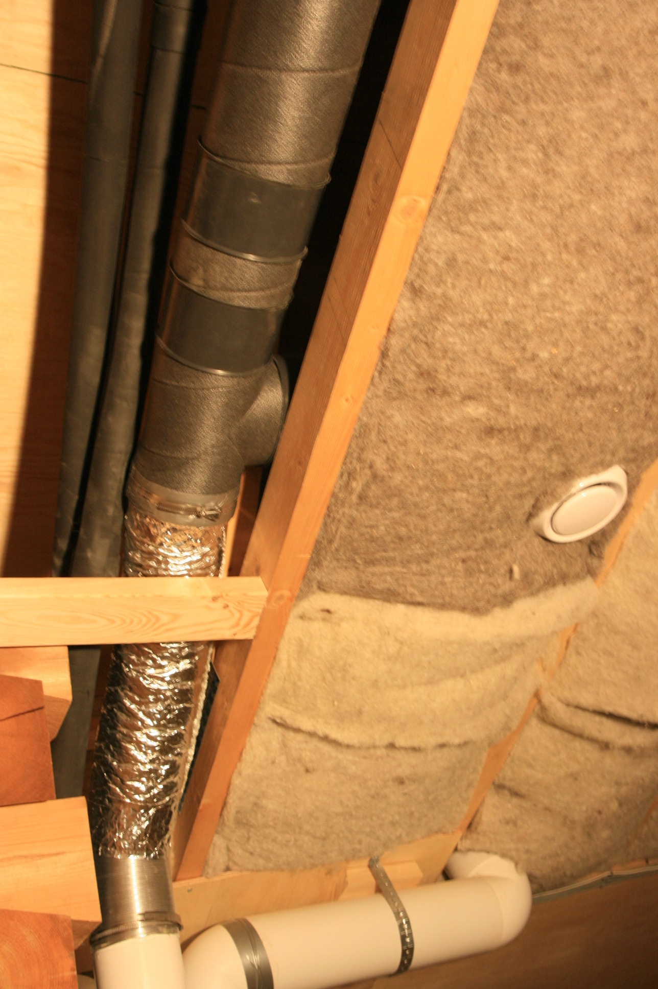
Our house has a roof angle of around 22 degrees. Standard heat recovery system pipework comes with 45 degree or 90 degree bends so something flexible was needed to join vertical runs coming off the top of the heat recovery unit that go across the top of the house by passing through the rafter space. These runs have to be made with insulated pipe because as the pipe goes into a cold space above the sheepswool insulation there is a risk of condensation if the air has sufficient moisture in it.

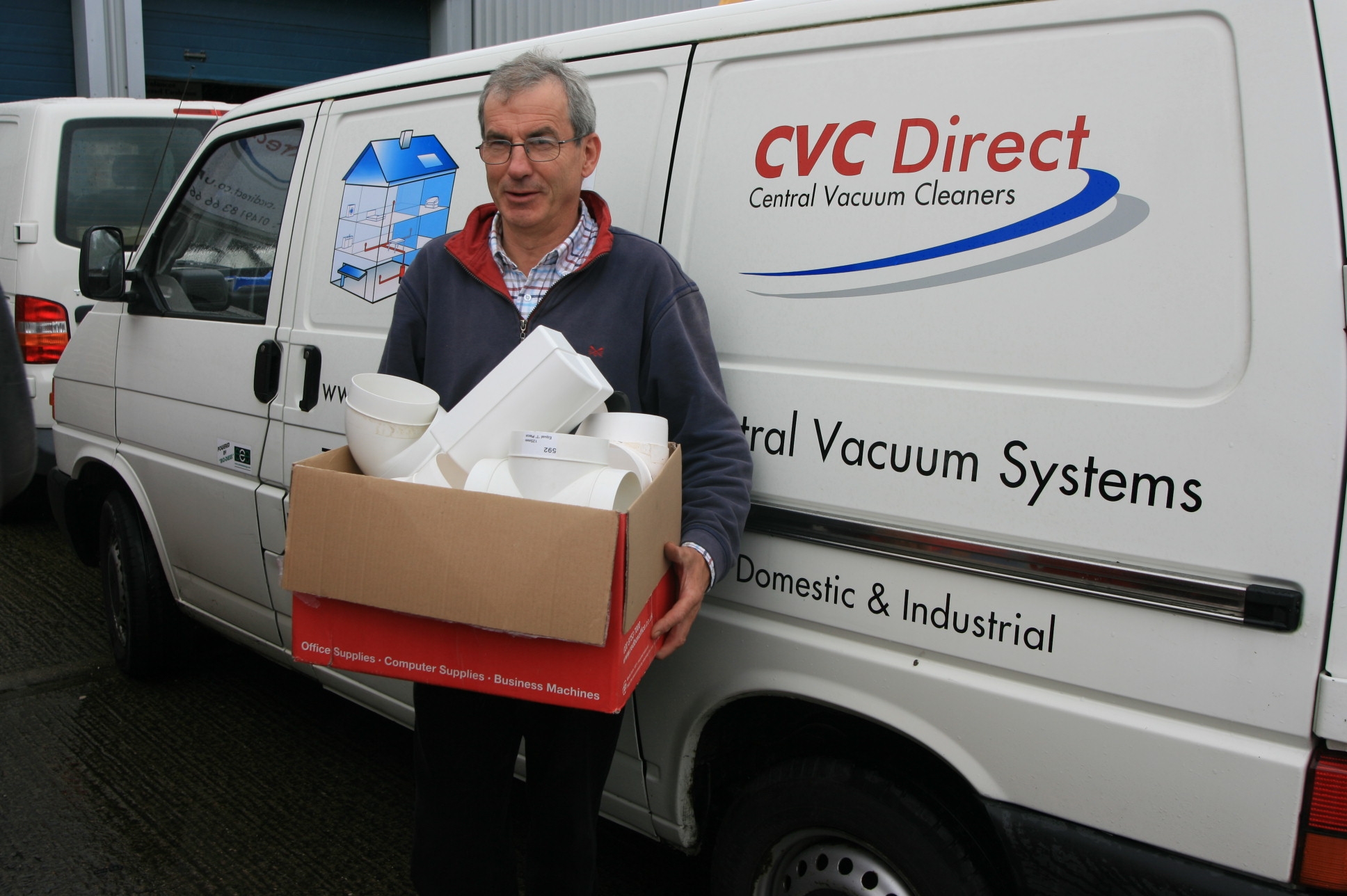
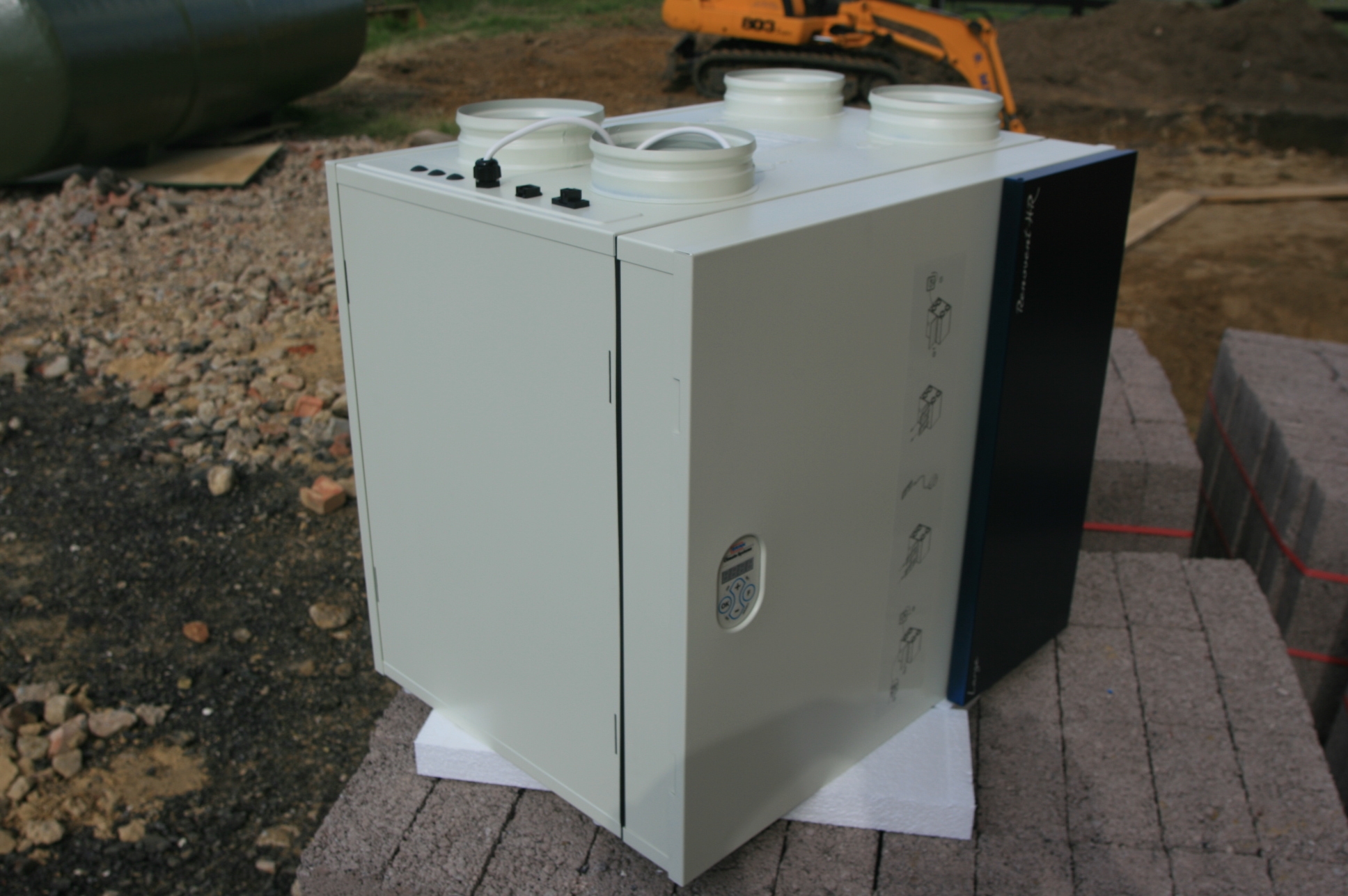
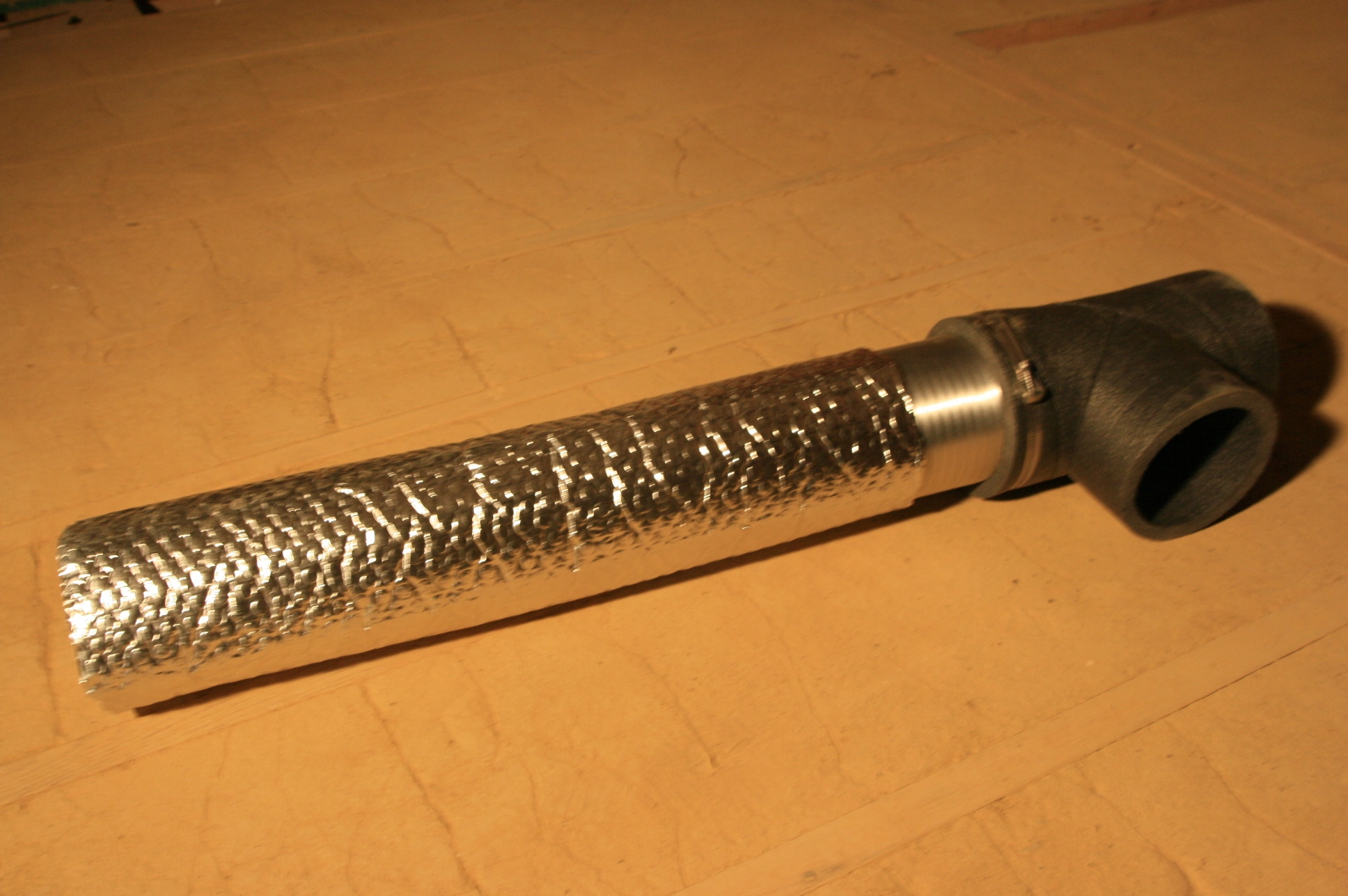
So on our last visit to CVC (www.cvcdirect.co.uk) we got a short length of flexible Aluminium ducting, some worm drive clips and some bubblewrap and aluminium foil insulating sleeve and assembled it, using the foil tape to secure the outer insulation. Here’s one we prepared earlier.

heat-recovery-in-bends-assembled.jpg

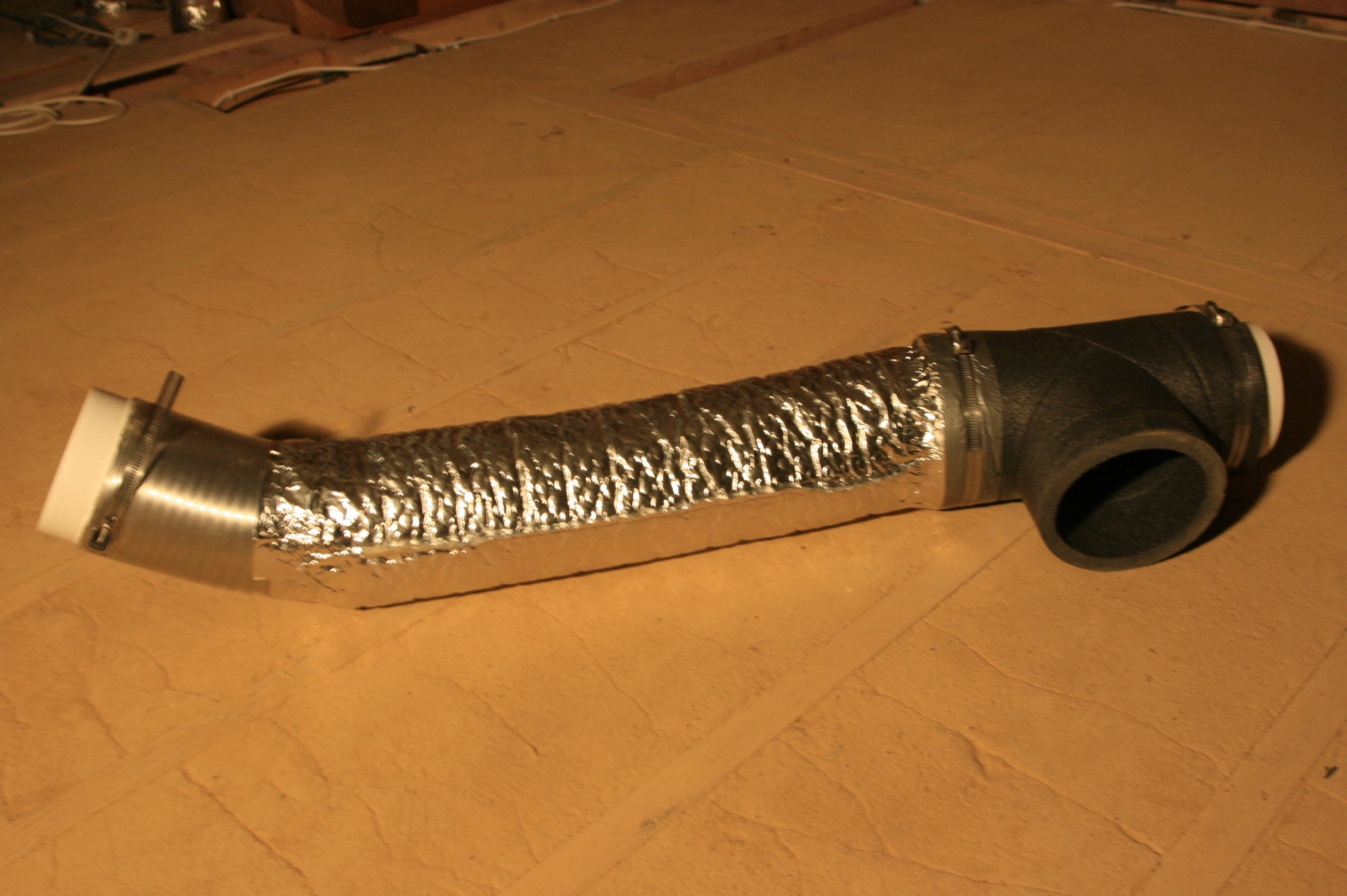
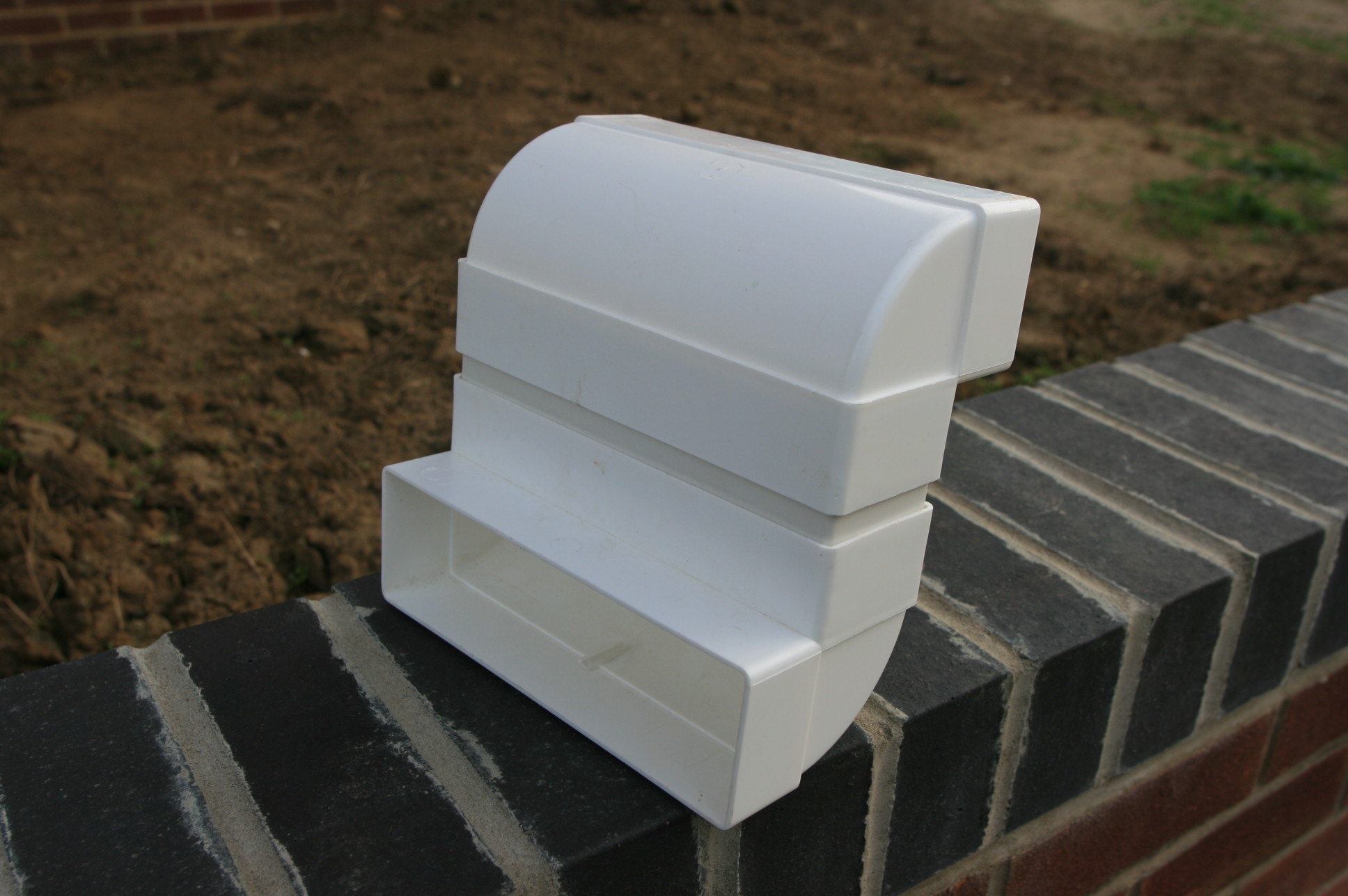
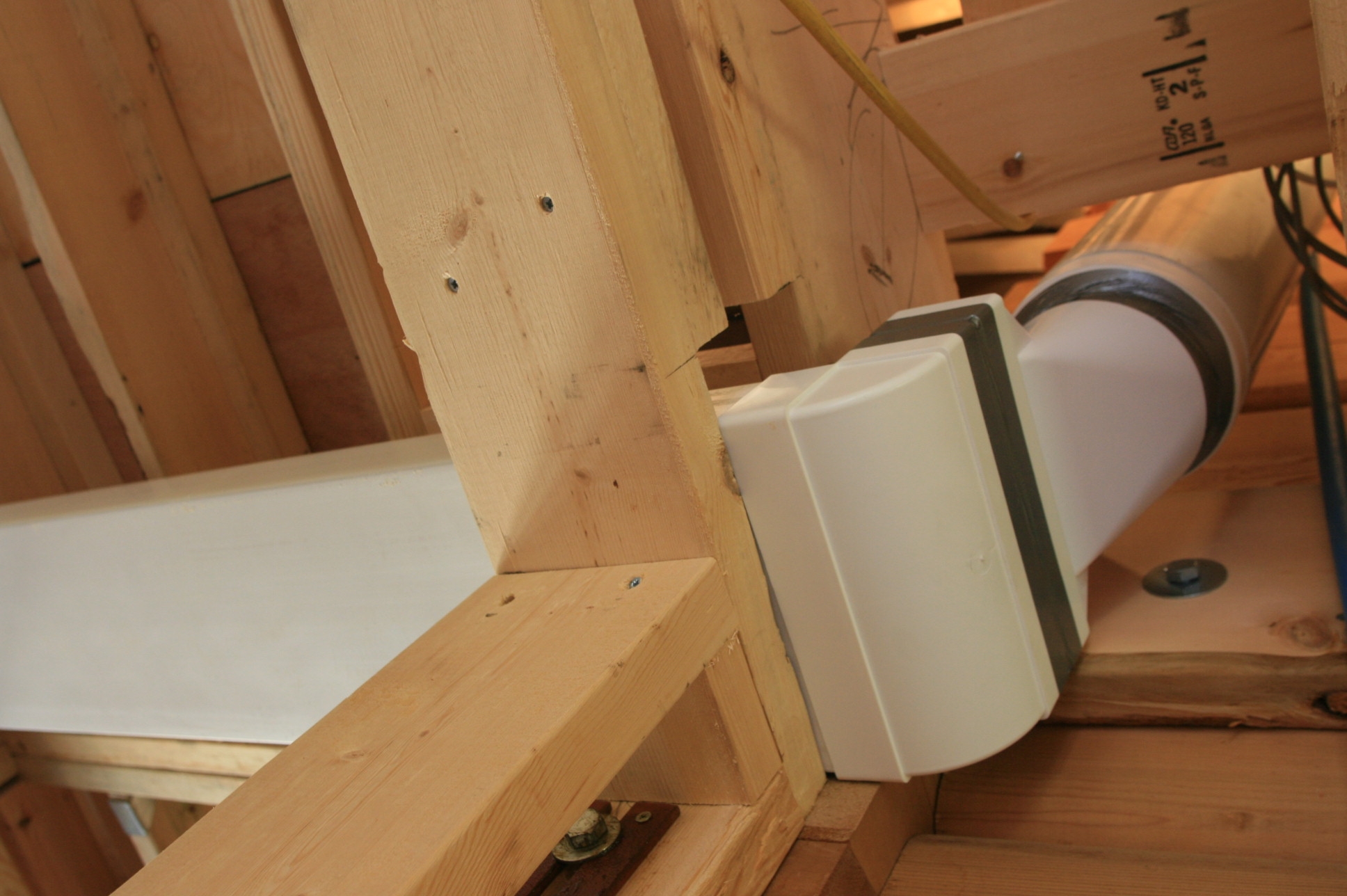
This then slid into position a treat and bends nicely to fit into the busy space between the rafters. The Aluminium pipe needs a white plastic connector on the end to enable it to fit into the 125mm white plastic pipe coming up from the Heat Recovery Unit.

heat-recovery-bend-in-position.jpg

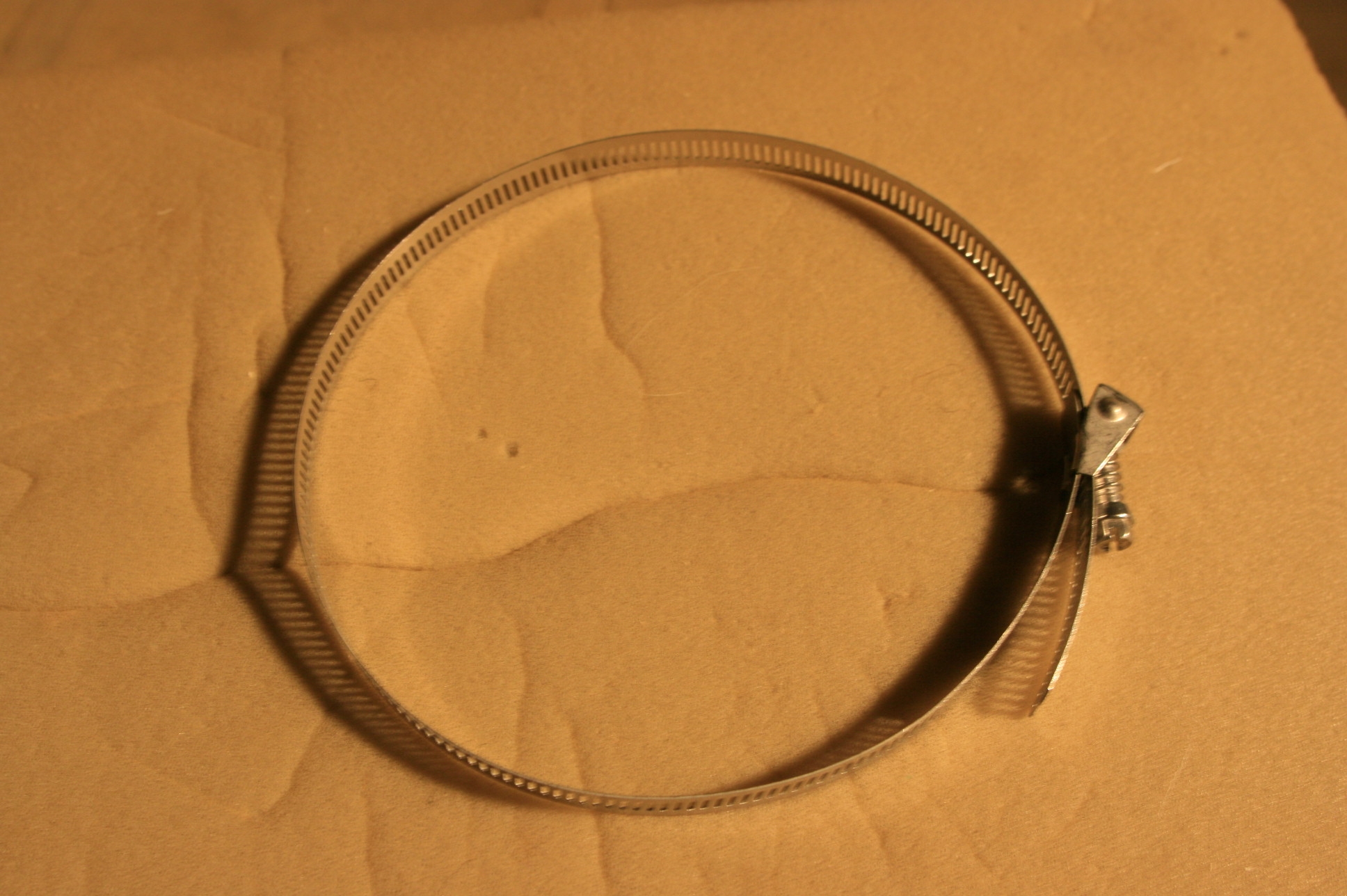
The giant worm drive clips supplied are really easy to use compared to a conventional clip of this sort.

heat-recovery-jubilee-clip.jpg 
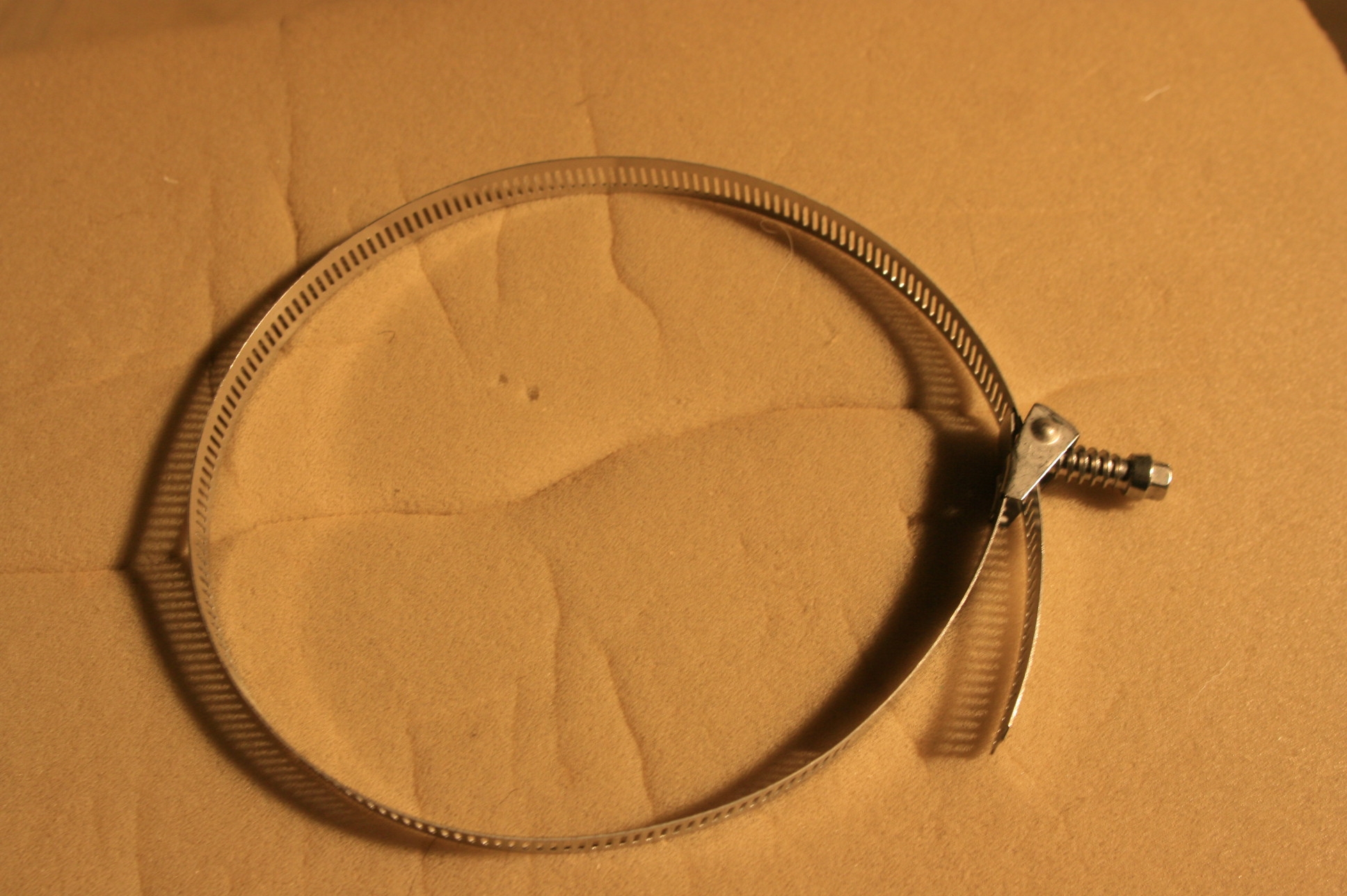
They have a hinging screw, so in a confined space you don’t have to spend ages doing them up, just close the clip as much as you can by hand, swing the hinging screw into position to engage the pierced stainless steel band on the screw thread and tighten the last bit with a screw driver.

heat-recovery-jubliee-clip-assembled.jpg

Sep 5 2008

Heat Recovery and Central Vacuum returns

2

Tim Bartlett from CVC Systems takes back a box of odds and sods! central-vacuum-system-returns.jpg When you are working in three dimensions with pipework  for the heat recovery and central vacuum systems it is difficult to anticipate all the bits and pieces you might need, how much, what sort etc.

So it was great to be able to work with CVC and take unused parts back for credit as we got to the end of the job. This saves lots of unused plastic items sitting around unused which is good for the environment as less has to be made for the next customer!

Also as we go along we discovered new fittings that solved problems we discovered which we swoped for some of the returned bits and you can see some of them next week. If you are excited by pipework problems, this is the blog to watch!

Sep 3 2008

Heat Recovery Ducting

-

heat-recovery-rectangular-duct.jpg Here is a handy bit of ducting! Two 90 degree rectangular bends joined by a bit of rectangular pipe to get into those awkward bits.

Aug 22 2008

Heat Recovery final fitting

-

heat-recovery-sub-assemblies.jpg Now tht the ceiling plasterboard is going up, we are gluing up our duct work for the heat recovery and comfort cooling sytems. here is a collection of “sub – assemblies” that have been glued up. This just leaves us the remaining joints to glue or tape with duct tape once the assemblies are slid into place.

The system has taken a lot more time to think through the routing than expected. Working in 3 dimensions with such large pipework is a challenge, even in a new house. It is certainly worth getting the basic pipe runs in place before the plumbers and electricians get too far into the job because firstly you may have to have boxing in in places that might be helpful for them, and it stakes your claim on bits of space!

Aug 7 2008

Heat Recovery and Comfort Cooling in place

-

heat-recovery-in-place-7th-aug.jpg There was just enough space in the eaves to fit the heat recovery and the comfort cooling units. The comfort cooling unit on the right re-cycles air in the room, passes it over a heat exchange matrix which uses the cold return feed from the heat pump to reduce the air temperature by about 7 degrees. So the return side of this has to be insulated (the sliver stuff). The heat recovery pipes only have to be insulated where it goes into “cold” spaces such between the rafters above the sheepswool insulation.

Jun 28 2008

Heat Recovery pipework

-

heat-recovery-change-of-shape.jpg You can run the pipework in a variety of sizes. Main ducts are 150mm in diameter close to the unit, branching off to 125mm and then sometimes down to 100mm if you wish. In some tricky places you can use the rectangular equivalent of these round sizes to get round corners or reduce the size of pipwork that you are boxing in.

We finally gave in and decided to include two fitted cupboards which will hide pipe runs between the first and second floors and here the rectangular section is a neat space saver. 

Jun 27 2008

Heat Recovery Distribution

-

heat-recovery-distribution.jpg Here’s some 125mm diameter heat recovery pipework over the kitchen. It’s one thing working out what you need on paper, but working in 3D with the really thing is very different, and you find you are ordering more and more pipes, bends, connectors etc.

Initially we thought the best place for the heat recovery unit would be over the kitchen and bathrooms, but after working on it in that position for a day there was a sudden eureka moment when we realised that putting it on the other side of the house would shorten 2 of the 4 pipe systems (fresh air inlet and “wet” air exhaust) substantially so we remounted the unit and started our three dimensional puzzle afresh. 

Jun 24 2008

Heat Recovery

-

heat-recovery-unit.jpg We have been convinced that putting heat recovery in the house will improve the energy efficiency and air quality in the house. So here is the unit, which will take warm and smelly air from “wet rooms” such as the kitchen, bathroom, WC etc, take the heat out of it using a heat exchanger and transfer that heat into fresh air from outside that is then fed into the “dry” rooms, lounge, bedrooms etc.